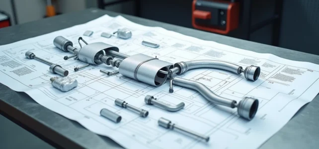
The exhaust line refers to the set of elements fixed under the body of a vehicle, from the collector bolted to the cylinder head to the rear outlet pipe. In a classic diagram, four or five blocks are enough to represent the path of the gases. An exploded view, like the one used by equipment manufacturers in their catalogs, sometimes breaks down more than fifteen distinct references for a single line, including flanges, clamps, rubber mounts, and suspension springs.
Back pressure and gas flow: what the exploded view reveals about engine operation
Before naming each part, it is essential to understand the physical constraint that governs the entire line: exhaust back pressure. When the burnt gases leave the cylinders, they must evacuate quickly enough not to hinder the next cycle. If a section is blocked, the pressure rises back toward the engine and directly restricts power.
See also : How much does it cost to find an imam for a Muslim religious wedding?
In an exploded view, each connection, each change in tube diameter, and each flexible bellows represents a potential friction point. This is why catalogs indicate the exact inner diameter of each section. A difference of a few millimeters between two connected tubes is enough to create turbulence that increases back pressure.
This reading of the diagram changes the perspective: instead of seeing a succession of “boxes” connected by tubes, one identifies a conduit whose section and sealing condition the engine’s efficiency. An car exhaust line diagram on Mécamobile details each sub-assembly with its dimensions, allowing for the identification of these diameter variations piece by piece.
Recommended read : Discover who shares Caroline Munoz's life: a portrait of her partner

Flexible braid and rubber mounts: the forgotten parts of the exhaust line diagram
Online guides dedicate most of their content to the collector, the catalytic converter, and the muffler. The flexible braid (also called a bellows or compensator) is rarely highlighted, even though it is one of the most common failure points on vehicles over five years old.
Located between the collector and the downpipe, the braid absorbs engine vibrations to prevent them from transmitting to the rest of the line. It consists of a metal mesh woven around a corrugated tube. When it cracks, gases escape before the catalytic converter, producing a characteristic metallic noise and skewing the lambda sensor readings.
Rubber mounts and attachment points in the exploded view
The exhaust line weighs several kilograms and constantly undergoes the movements of the body. The rubber mounts suspend the entire assembly under the floor. In an exploded view, they appear as small droplet or lyre-shaped pieces, attached to rods welded to the mufflers.
Their degradation often goes unnoticed. A hardened or cracked mount allows the line to “hang” by a few centimeters, altering the angle of the connections and accelerating corrosion at the junction points. Identifying their exact location on the exploded diagram allows for inspection during a vehicle check.
Catalytic converter, DPF, and GPF: differentiating pollution control units in an exploded view
These three components look similar in a simplified diagram: oblong housings inserted into the line. The exploded view clearly distinguishes them thanks to their connections and relative positions.
- The catalytic converter is located closest to the collector, as it requires high temperatures to convert nitrogen oxides, carbon monoxide, and unburned hydrocarbons. In the diagram, it is connected to the downpipe by a bolted flange or a conical gasket.
- The particulate filter (DPF) is used in diesel engines. Positioned just after the catalytic converter, it traps soot and must reach very high temperatures to regenerate. Its casing is often larger than that of the catalytic converter, making it identifiable in the exploded view.
- The gasoline particulate filter (GPF) serves a similar function in direct injection gasoline engines. More compact, it is sometimes integrated into the same housing as the catalytic converter, complicating its identification in a non-exploded diagram.
In a professional exploded drawing, each block carries a distinct manufacturer reference. This granularity prevents ordering a catalytic converter when the issue lies with the O-ring located between the catalytic converter and the DPF.
Corrosion and materials: reading a diagram to anticipate wear
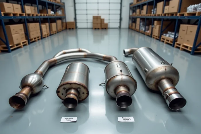
Exhaust parts do not age at the same rate. The exploded view helps to understand why, as it distinguishes the materials used for each section.
The front section (collector, braid, downpipe) endures the highest temperatures. It is generally made of cast iron or refractory stainless steel. Corrosion here is primarily thermal: cracking due to heating and cooling cycles.
The rear section (intermediate and rear mufflers, connecting pipes) is more affected by wet corrosion. Water from the condensation of gases stagnates in low points. In an exploded view, these low points correspond to the lowest areas of the layout, often at the level of the intermediate muffler.
Aluminized steel, galvanized steel, or stainless steel
Equipment catalogs specify the material of each reference. An aluminized steel muffler resists external corrosion better than a raw steel model, but not as well as a stainless steel equivalent. Stainless steel significantly extends the lifespan of the rear section, which explains the price difference between two references compatible with the same vehicle.
Identifying the material on the exploded view allows for a choice between an original part and a suitable equivalent, depending on the remaining mileage expected for the vehicle.
Technical inspection and exhaust: what the inspector really checks
During the technical inspection, the examination of the exhaust line focuses on sealing, attachment, and noise level. Since the implementation of technical inspections for two-wheelers, components related to the exhaust are also subject to specific checks regarding noise pollution and emissions at the exhaust.
For cars, a sealing defect at a flange gasket or a punctured braid leads to a re-inspection. The exploded view serves here as a map: by identifying the exact part in question, one avoids replacing an entire section when only a clamp or a gasket is needed.
Reading an exploded diagram of the exhaust line remains the most reliable way to link a symptom (noise, smell, loss of power) to a specific part. Each reference carries a number, a material, and a position, three pieces of information that transform an approximate diagnosis into a targeted order.